Architectural Innovations
Masonry movement joints are one of the most misunderstood and underappreciated technical issues in the masonry industry. The lack of properly located, detailed, specified, and installed masonry movement joints can result in “masonry failures.” However, most masonry deficiencies due to movement issues are not performance issues with masonry units or systems, but rather can be attributed to "design failures."
Who is responsible?
According to the national masonry model code, as referenced by the International Building Code, mandatory requirements checklist for designers, in the specification section TMS 602 of “Building Code Requirements and Specification for Masonry Structures” (TMS 402/ACI 530/ASCE 5 and TMS 602/ACI 530.1/ASCE 6), Page S-31, Part 3.3 F.7, designers are required to “Indicate type and location of movement joints on the project drawings.” Furthermore, TMS 402, Section 6.1.6.3 states it is the responsibility of the building designer to “design and detail the veneer to accommodate differential movement.”
Control Joints vs. Expansion Joints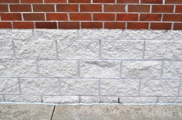
There are many types of masonry movement joints and movement control strategies, but the two most common are control joints in the concrete masonry unit (CMU) walls and expansion joints in clay brick veneers. In the past when CMU and brick walls were constructed as bonded composite walls, control joints and expansion joints needed to be coordinated and aligned through both the block and brick. In modern masonry cavity walls, these two different masonry wythes are connected with flexible connections so control joints in the CMU back-up wall can be located independently of the expansion joints in the brick veneer. It is recommended that structural engineers locate control joints in structural masonry wall for structural reasons, while the architects are free to locate movement joints in the veneer to address both functional and aesthetic priorities.
Common Mistakes
When masonry structural walls, partitions, or veneers crack due to the lack of masonry movement joints, not enough masonry movement joints, or the improper placement of masonry movement joints this is a design failure - not a masonry failure. When masonry cracks occur due to poor workmanship then the failure can be attributed to the mason – but this is rare.
The main mistakes designers make when locating movements joints are:
- relying on generic specification language to locate movement joints, instead of showing them on the building plans and elevations,
- locating control joints at the ends of masonry lintels in vertically reinforced masonry walls,
- not understanding movement control strategies for CMU veneers,
- not understanding industry recommendations for locating veneer movement joints in relation to outside corners,
- not locating movement joints at inside corners,
- not understanding the use of isolation joints,
- not understanding how veneer lintel type influences placement of vertical movement joints at or near window openings,
- not detailing proper expansion joint width in clay brick veneers,
- not having horizontal movement joints between different veneer material types,
- and not having movement joints at window and door frames.
Movement Joint Failures
 Failure #1: Specifications Approach to Locating Movement Joints
“Locating” masonry movement joints with generic specification language does not give masons enough information to make decisions about where to locate movement joints. For example, common specification language typically does not address different industry guidelines for movement joints to be spaced closer in clay brick veneer with multiple openings as opposed to walls without any openings. In addition, a general specifications approach to movement control may erroneously negate the structural capacity of masonry if a mason unknowingly segments a CMU shear wall. Therefore, it makes sense for the structural engineer to locate movement joints in structural masonry walls and the architect to locate movement joints strategically in the veneer for both functional and aesthetic reasons.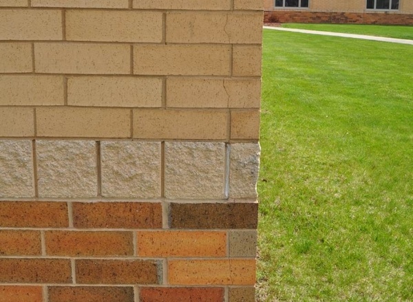 Failure #2: Vertical Control Joints at Ends of Masonry Lintels
When masonry lintels are used to span openings in vertically reinforced masonry walls, vertical control joints should not be located at the end of the masonry lintel when vertical reinforcement is located at jambs of openings. In this scenario, the vertical reinforcement at opening jambs is bonded integrally with the horizontal reinforcement bar and grout of the masonry lintel – therefore a control joint in this location cannot move properly. In vertically reinforced masonry walls with masonry lintels, vertical control joints should be located between openings, or at least 24-inches away from the opening – not to exceed 25-feet on-center (Figure 1). 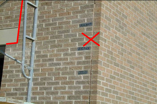 Failure #3: Not Understanding Concrete Masonry Veneers
When masonry veneer is comprised of concrete masonry units, there are special movement control guidelines to be considered as outlined in the National Concrete Masonry Association (NCMA) TEK 10-4 (2001) “Crack Control for Concrete Brick and Other Concrete Masonry Veneers.” These guidelines are can be very different than movement control strategies for clay brick veneers in some environments (Figure 2). 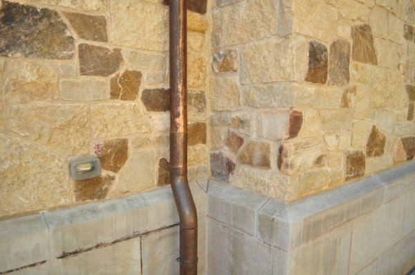 Failure #4: Movement Joints at Outside Corners
Vertical masonry movement joints should be located on both sides of outside wall corners so the distance between them does not exceed the appropriate spacing between movement joints for that specific project. Also, when locating a movement joint near a door or window, that is next to the corner, the movement joint should be located on the corner side of the opening (Figure 3a & 3b). Movement joints do not need to be located at the outside corner of masonry walls. In fact, doing so will make the masonry wall look panelized, that will impact the aesthetics of the building (Figure 4). 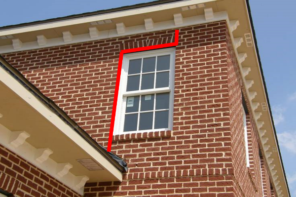 Failure #5: Not Locating Movement Joint at Inside Corners
Unless there are special circumstances, a good general rule-of-thumb is to put vertical movement joints at the inside corner of masonry walls (Figure 5). This is a good place to start when locating movement joints on either building plans or elevations. Then, the distance between them can be calculated and decisions can be made to segment the remaining wall length.
Failure #6: Isolation joints
Isolation joints in masonry walls separate portions of walls that have different heights, volume, loads, and bearing conditions (Figure 6).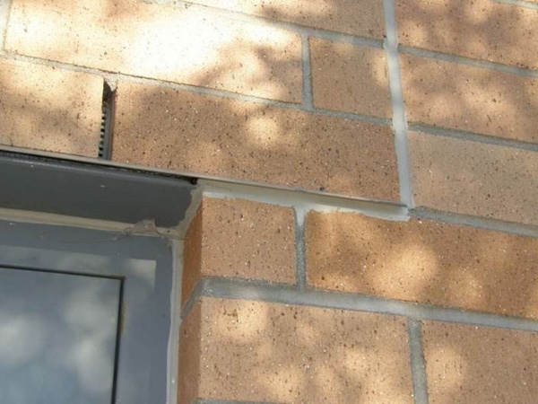 Failure #7: Veneer Lintels
There are two types of masonry lintels: loose and fixed. Fixed lintels are those that are connected to the lintel in the back-up wall – as is typical for larger spans. When masonry veneer is supported with fixed lintels, a portion of the veneer will bear of the structural steel and the nearby portion of wall will bear on the foundation or some other bearing point. Therefore, when portions of the veneer have different bearing points, those portions of the veneer are often separated with a vertical movement joint (Figure 7). There can be exceptions to this recommendation when there are stacked openings, with fixed lintels, in multi-story elevations. 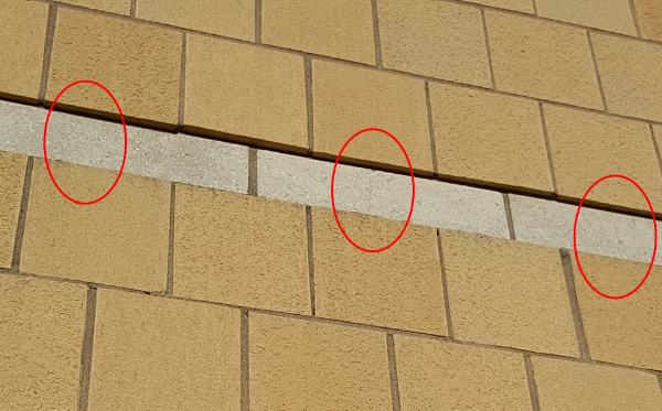 Failure #8: Expansion Joint Width
Expansion joints are movement joints than pass through materials that have properties of expansion – such as clay brick. With expansive clay bricks on both sides of an expansion joint, these joints should be installed ½-inch wide to let them reduce down to 3/8-inch to match typical mortar joints width. Unlike, control joints, expansion joints need to be clear of mortar droppings and be adequately sized to allow the joint to compress without over-stressing the back rod, joint filler strips, or creating pressure points on the brick.
Failure #9: Movement Joints at Different Materials
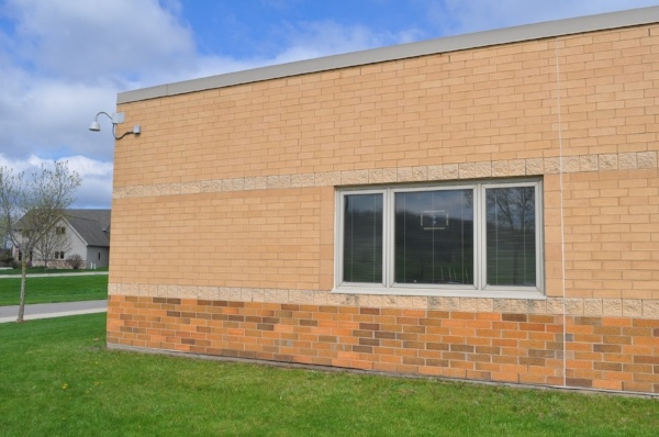
When bands of differentially moving materials are used in the same veneer wall plane, provisions should be made to accommodate the differential movement with bond breaks, back rod, and sealant (Figure 8). With single-course bands of masonry, care should be taken to attach masonry bands to the building by either connecting the band to the support wall with veneer connectors in the head joints of the band, or only breaking the bond at the top joint of the band. Another strategy for this condition is to achieve the banding aesthetic with similarly moving masonry materials of different size, color, or texture so there is no differential movement to address.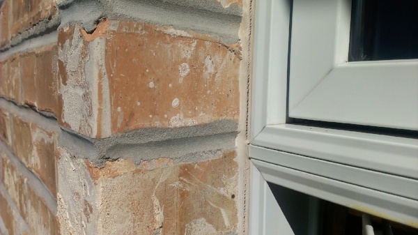 Failure #10: Gaps at Windows and Doors
Designers should illustrate and dimension gaps at the interface of masonry veneers with window and door frames. Without this dimensioned gap, masons may build too tight up against frames, resulting in inadequate space to install appropriate backer rod and sealant joint for a properly proportioned sealant joint (Figure 9a).
Conclusion
Most cracks in masonry walls are not “masonry failures” but rather a failure of the building designer to adequately specify, detail and locate masonry movement joints in the construction documents. The code clearly states that it is the responsibility of the designer to locate movement joints - not the mason. Masons do not have enough information about building loads, environmental conditions, product specifications, and aesthetic intent of the designer to locate movement joints.
Note: This article first appeared in RCI Spring 2016.
Pat Conway, International Masonry Institute


.png)

