By Pat Conway, AIA
As designers and building owners place increased demands on exterior walls to isolate the outside climate from the interior controlled environment, exterior walls’ capability to provide long-term assured performance must grow. As building enclosure design evolves, it is becoming more evident that important attributes of durable exterior cavity walls, in wet climates, must include the ability of the exterior wall to drain and dry quickly to protect the wall assembly from moisture-related issues.
CAVITY WALL EVOLUTION
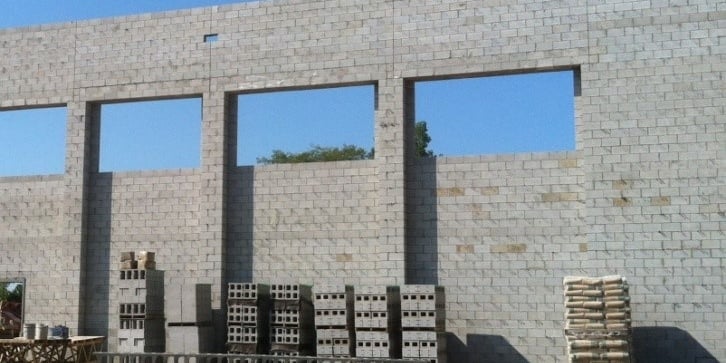
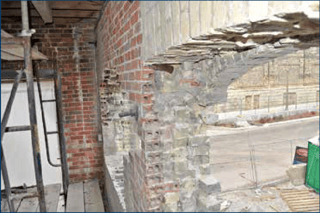
Historically, exterior masonry walls managed water by utilizing an abundance of mass to absorb moisture from the environment and then release it back slowly by random drainage and evaporation when the exterior relative humidity allowed. Typically, bulk water did not reach interior surfaces of thick mass walls due to the multiple masonry wythes, each with their inherent high moisture-storage capacity. Additionally, the drying efficiency of uninsulated mass-masonry walls is aided by the passage of interior energy out through the mass.
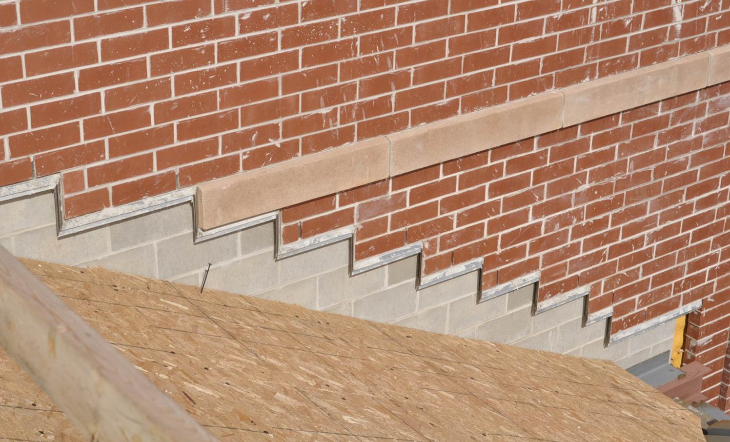
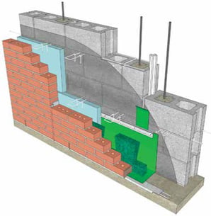
Today, thick mass masonry walls have been replaced with thin, energy-efficient and economical masonry cavity wall construction with internal water and air barriers, continuous insulation, and air space between the structural support wall and the exterior veneer. This modern wall assembly has isolated the veneer to experience more thermal and material movement, moisture-related stresses, and staining potential than massive masonry walls. Adding to the challenge of designing durable exterior wall systems, structural masonry support walls are sometimes replaced with moisture-sensitive materials such as wood and other sheathing products and associated framing. All these factors make rapid drainage and drying of exterior wall systems even more vital.
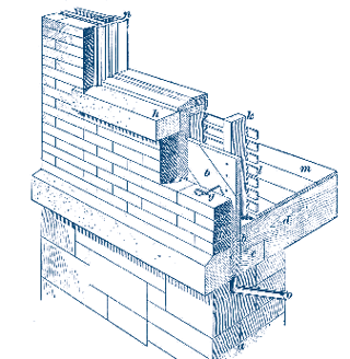
CAVITY WALL TYPES
Today there are three main types of cavity wall design:
- Unventilated
- Pressure-equalized
- Ventilated
UNVENTILATED CAVITY WALLS
The roots of modern cavity wall design can be traced back to the late 1800s, when wall systems started to become less massive, due to better material strength, improved understanding of the system, and a desire to reduce material cost, increase speed of construction, and minimize thermal and moisture transfer across the wall. For nearly 100 years, unventilated cavity walls were the norm until the mid to late 1900s, when building designers started to experiment with alternative design strategies to refine moisture, staining, and energy management methods for cavity walls by introducing upgraded wall assembly components and advanced moisture control design strategies such as pressure-equalized rainscreen wall concepts.
PRESSURE-EQUALIZED CAVITY WALLS
In theory, pressure-equalized rainscreen walls are designed to allow enough exterior air into the wall cavity to create back pressure to reduce or eliminate the positive force of wind-driven rain against the veneer. However, in reality, there are too many variables required in order for a system to be designed and installed flawlessly and achieve a true net-zero pressure differential across a veneer. To achieve a pressure-equalized rainscreen wall, the wall design needs to address:
- The rigidity of the support wall
- Actual air barrier continuity and tightness
- The weep vent type/spacing/location in the wall
- A weep-vent-free area of venting
- Increased modern air space recommendations
- Wall cavity baffle airtightness
- Mortar droppings
- Landscaping mulch
- Overall workmanship
Pressure-equalized rainscreen walls can be achieved, but not without proper calculations, design, quality control, instrumental verification, and skilled craftworkers. Because of the complexity of pressure-equalized rainscreen walls and the high level of wall assembly coordination required, it is ideal to have one contractor install the entire exterior wall assembly for single-source responsibility.
VENTILATED CAVITY WALLS
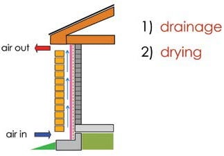 A more realistic and economical approach for increased moisture management in exterior cavity walls is the use of a ventilated cavity wall concept. Ventilated cavity walls use some similar components of pressure-equalized rainscreen walls, but without the calculations, small air space chamber requirements, observation, testing, and related cost. In fact, some building scientists have stated that many, if not most, pressure-equalized rainscreen walls are not properly designed or executed and are just functioning as “well-ventilated cavity walls,” anyway.
A ventilated cavity wall works on the simple premise of letting air into and out of the wall cavity through weep vents strategically located both low and high in veneer panels to connect the internal wall cavity with the exterior environment. This connection promotes drying of the wall assembly as moisture is dissipated to the exterior through vents in the veneer. Venting of the wall cavity in wet climates creates walls that are more resilient with less moisture-related issues such as spalling, cracking, or staining. In some cases, the introduction of wall cavity venting to an existing unventilated cavity wall has helped alleviate or eliminate chronic efflorescence, since salt-saturated moisture does not have time to form in abundance or migrate to the surface of the veneer.
At a time when wall cavities are becoming thinner and wall accessories are being “ value-engineered” to fit tight budgets, increased drying capacity of wall cavities can help evaporate free or trapped moisture from within the wall assembly to keep moisture-sensitive support wall sheathing products and internal wall components such as insulation and veneer connectors at acceptable humidity levels. As early as 1964, Canadian Building Digest 50, in “ Principles Applied to an Insulated Masonry Wall,” stated, “ Corrosion of ties can be greatly improved by proper design that avoids serious or prolonged wetting.”
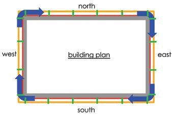 For purposes of wall assembly drying only, airflow direction and wall cavity chamber sizing do not matter. However, when letting an abundance of air into the wall cavity, air space compartmentalization should be considered to moderate pressures within the wall cavity and reduce localized high-pressure differentials across the cladding at wall panel edges and corners. Also, vertical cavity air baffles will prevent moisture-laden air within the wall cavity from traveling horizontally to possibly spread moisture-related issues throughout the exterior wall system. For example, if interior air from a highly humidified portion of the building is leaking into the wall cavity, this air could then move horizontally to express staining or corrosion in another part ofan adjacent building elevation. Horizontal cavity air baffles often occur naturally at veneer shelf angles.
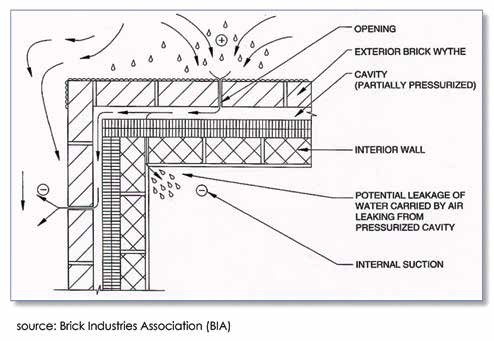 With ventilated cavity walls, airflow convection loops within the wall cavity will occur naturally due primarily to wind pressures, air pressure, building geometry, and stack effect phenomenon. For example, when air in a wall cavity is heated by solar gain, an upward vertical flow of air may develop due to warm air rising in the wall cavity and exiting through upper weep vents. Horizontal convection loops can also develop due to the temperature of one building elevation being changed more quickly than a perpendicular elevation, such as when an eastern building elevation is warmed by the morning sun, while air within the southern, western, and northern wall cavities remains cool. For this reason, vertical wall cavity air baffles are a good idea at building corners. When wall cavity airflow is not controlled around corners, the influence of windward, leeward, and turbulent wind pressures could possibly create forces at the outside building corners to allow exterior moisture into the wall cavity.
The main components of ventilated cavity walls are: a vented cladding, air space behind the cladding, air barrier on the exterior side of the support wall, and through-wall flashing. If there is wall cavity insulation, then the insulation should be made continuous at joints and penetrations with tape, spray foam, or other means so air is not allowed to circulate between the insulation and the support wall, 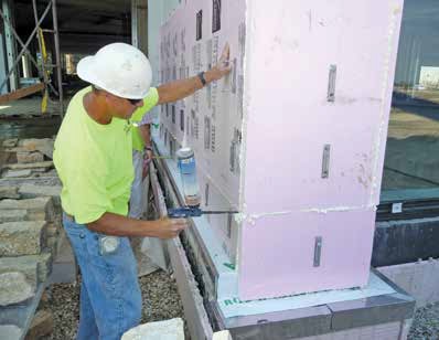 which can diminish the insulation R-value.
To increase drying capacity of an exterior wall assembly, it is desirable to let outside air into the wall cavity, but it is not a good idea to allow this air with associated moisture, dust, or noise to enter the building. This is why the use of a ventilated wall strategy should only be used when a continuous and durable air barrier is applied to the exterior side of the support wall.
When air is allowed to enter the wall cavity for drying purposes and not pressurization, the spacing of weep vents is not critical as long as it conforms to industry recommendations, standards, and local and national codes such as the Building Code Requirements and Specification for Masonry Structures (TMS 402/ACI 530/ ASCE 5 and TMS 602/ACI 530.1/ASCE 6), Section 6.1.6, which states, “Design and detail flashing and weepholes in exterior veneer wall systems to resist water penetration into the building interior. Weepholes shall be at least 3⁄16 in. (4.8 mm) in diameter and spaced less than 33 in. (838 mm) on-center.” The Canadian Building Code requirement is governed by CSA A371-04, Masonry Construction for Buildings.
Since the national model masonry code does not address ventilated cavity wall strategies, it should be noted this document still refers to small-diameter “ weepholes” as opposed to larger “weep vents” that are more open to air flow. For the purposes of unventilated cavity wall design, small-diameter weepholes and rope wicks may perform to a certain degree, but for ventilated cavity wall design, full-height head joint weep vents in modular brick veneers or partial-height inserts in larger veneer units are desirable.
When introducing intentional openings in a veneer with weep vents, common sense suggests these openings should be resistant to wind-driven moisture. When using completely open head joints (without an insert) as weep vents in a masonry veneer, the bottom of the open head joints located in the upper portions of wall panels can be installed with a beveled mortar wash to resist upwardly driven rain on a saturated wall. For weep vents with an insert, the insert itself can be designed to deflect moisture.
Many weep vents on the market today are manufactured to allow ample free ventilation area while resisting wind-driven rain with materials such as entangled polymer mesh, cellular plastic, or other physical configurations. Furthermore, openings ⅜ in. (10 mm) or greater will not allow a film of water to form over them, thus negating the idea of water being blown into a weep vent. There is no known evidence that upper weep vents have caused a negative moisture problem. On the contrary, it is a common design philosophy and field observation that with ventilated cavity walls, the increased drying capacity of a ventilated cavity wall is greater than the potential wetting potential, and is beneficial to the performance of the exterior masonry veneer and internal wall components.
 Pat Conway is a registered architect in Wisconsin and a member of the American Institute of Architects. He is co-director of the International Masonry Institute’s (IMI’s) national masonry technical team, IMI's Director of Architectual Education, a faculty member of IMI’s Contractor College, and a provider of Craftworker upgrade courses. Conway is a frequent lecturer and author on numerous masonry subjects.
This article was first published in RCI's Interface March, 2016 magazine.
The original content can be accessed here.


