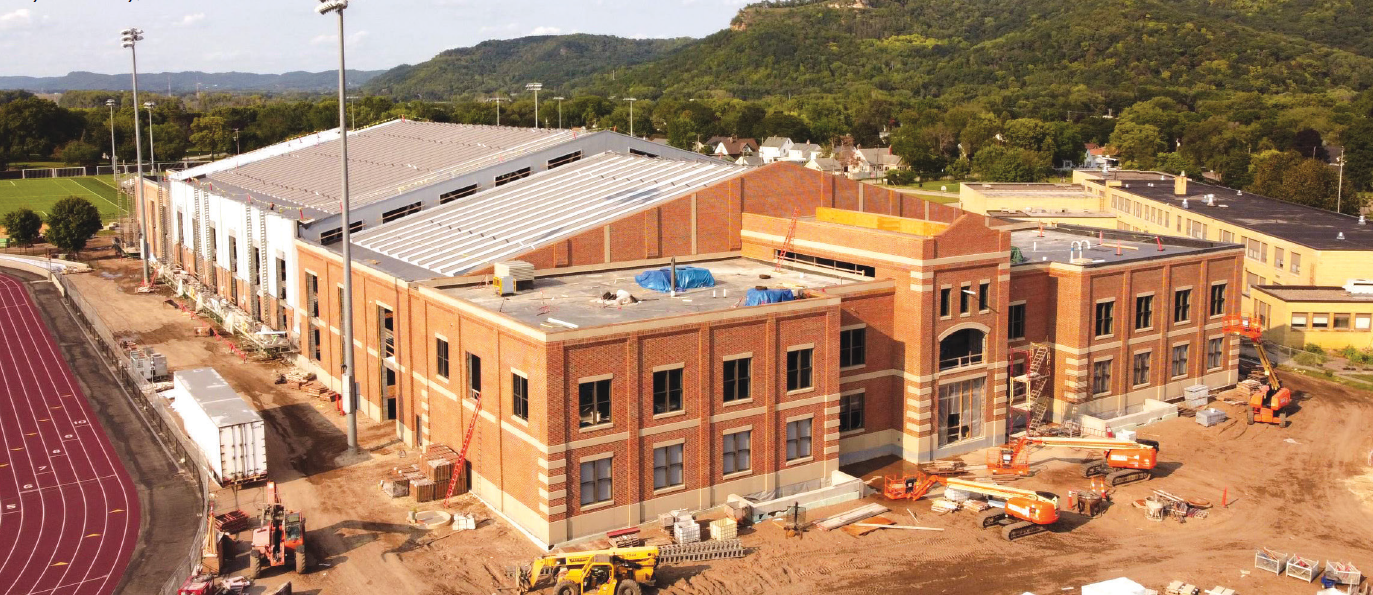
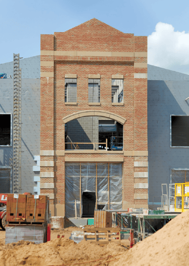
 Student Fieldhouse & Soccer Support Facility at the University of Wisconsin – La Crosse, under construction.
Posted with permission, STRUCTURE, May 2022.
The University of Wisconsin – La Crosse (UWL) is constructing a new $49 million, 144,000 gross-square-foot Student Fieldhouse & Soccer Support Facility for their campus. Masonry was the obvious choice for interior infill walls within the structural steel frame and key loadbearing walls. But what was not so apparent was how the mason contractor and design team would work together to develop creative uses of prefabricated masonry lintels, lightweight CMU, and a seldom-used alternative engineered method to eliminate or minimize the number of control joints (Figure 1).
Masonry Lintels
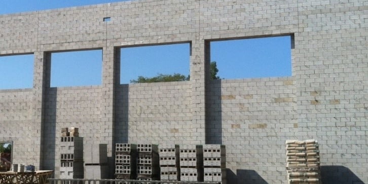
It is rare that a masonry lintel cannot be used to span openings in a CMU wall – even substantial openings. Products to con-struct masonry lintels are typically local, available, and less costly than structural steel lintels. In many scenarios, steel lintels may have to be delivered long distances and be a long-lead item that can negatively impact project sequencing and schedules. For added advantages, masonry lintels move at the same rate as surrounding masonry walls, eliminating potential cracking due to differential movement that occurs with steel lintels. More than ever, modern masonry lintel installation techniques are easy to support during installation, or they can also be prefabricated to eliminate the need for any temporary shoring (Figure 2).
 At the UWL Fieldhouse, project engineer Chad Allen with Oneida Total Integrated Enterprises (OTIE) states, “From the start of the project, we wanted to use masonry lintels wherever possible, and we were able to do so for most of the main portion of the fieldhouse. Masonry lintels off er a pure solution to spanning openings without introducing dissimilar materials. There were four larger arched openings in the CMU walls that needed to be precast. The precast concrete arches work well with a masonry wall for an easy-to-install and robust solution that we knew would not crack” (Figure 3, page 36).
Regarding masonry lintels, project architect Kyle Schauf, with HSR Associates out of La Crosse, gave this insight, “Over the years, we have learned from the International Masonry Institute’s (IMI) local Structural Masonry Coalition design services that con-tractors prefer masonry lintels from a constructability perspective. We like masonry lintels because it allows us to develop architectural details to minimize thermal transfer at window heads instead of having a structural steel beam bottom plate spanning from the inside of the building to the edge of the veneer” (Figure 4, page 36).
Lightweight CMU
Including the brick and cast stone veneer, the project’s masonry contract was nearly $4 mil-lion. There were over 144,000 CMU on this project; 33,000 were 16-inch CMU units. After being awarded the job, the contractor, Market & Johnson, worked with the design team to approve lightweight CMU for the entire project. Kevin Fabry, Masonry Project Manager for the Market & Johnson La Crosse office, says, “We prefer installing lightweight CMU because ultimately it is good for our masonry crew’s longevity and reduces chances for injuries and fatigue. For example, using a lightweight 16-inch CMU, one mason lifts approximately 1,000 pounds less per day!” Kevin continues, “Even though lightweight units cost a little more per unit, we see approximately a 10% installation increase and much better attitudes on the job site. When masons are happy, you always get a better product.
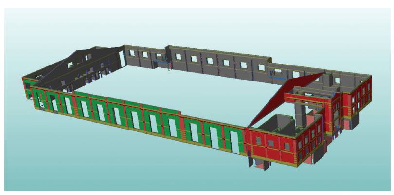
Figure 1. Model image from masonry contractor’s Tradesman 5.0N4 3D estimating software.
Additionally, lightweight CMU is easier to transport on-site. They chip less than normal-weight units, and using lightweight allows us to have lower mason-to-tender ratios, less rubbing, and less saw time and blades. ”Chad Allen (OTIE) states, “Obviously, during the design phase, we do not know what system/preferences the contractor prefers, so we default to normal weight products. Structurally, my concern was the block compressive strength and its impact on the masonry compressive strength. If the contractor could find a block that produced the required specified compressive strength of masonry (f´m), we would be good to go with the lightweight block. ”For efficient use of reinforcement bars and grout, the engineer for this project used the Unit Strength method to verify f´m compliance. The design value for masonry on this project was set at an f´m of 2,250 psi. Block strengths had to have a net compressive strength of at least 2,600 psi and Type S mortar to achieve the f´m value. Locally available off-the-shelf masonry units were used on this project without a cost premium, other than the upcharge for lightweight aggregate specific to this block supplier.
Alternative Engineered Method
Perhaps the most innovative masonry on this project was the use of the alternative engineered method for controlling masonry movement and eliminating cracking. On one wall that is 201.25 feet long by 61 feet tall at its gabled peak, the contractor, structural engineer, and IMI worked together to implement this movement control strategy to eliminate control joints. Because the wall had so many misaligned openings, accommodating CMU movement with standard control joint placement rules-of-thumb would have been challenging – both structurally and from a constructability perspective (Figure 5, page 37).
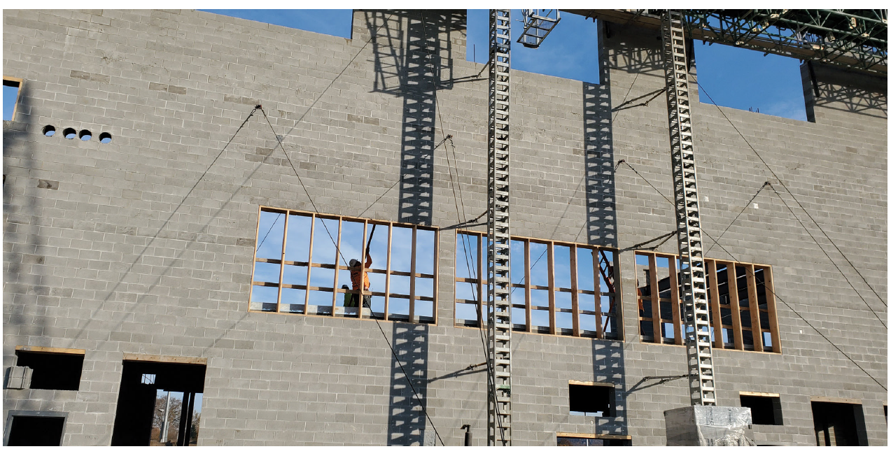 Figure 2. Robust shoring for continuous 7-course masonry lintel at large openings. This wall supports the roof (and drift load) on the opposite side of the wall. Other openings shored with a simple Z-clip and lumber technique.
The engineer referenced the National Concrete Masonry Association’s (NCMA) TEK 10-03, Control Joints for Concrete Masonry Walls – Alternative Engineered Method, to better under-stand this unique movement control strategy. With the installation of mid-wall bond beams at 48 inches on-center and the extension of masonry lintels the entire length of the wall, the structural engineer had enough horizontal steel in the wall to restrain masonry movement. This allowed the contractor to eliminate control joints! The contractor used self-consolidating grout to ensure proper grout flow with all the added grout and rebar in the wall. The contractor applauded this decision because it increased CMU installation production and decreased complicated and abundant temporary wall bracing, which aided site movement logistics.
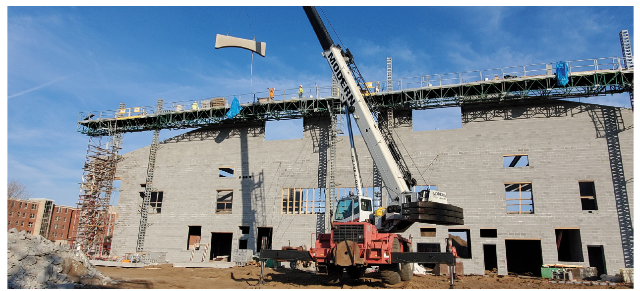 Figure 3. Precast concrete arch being installed on 16-inch CMU wall.
Structural engineer Chad Allen (OTIE) agreed, “For this particular wall, the engineering approach was actually much easier for everyone than figuring out where to locate vertical joints, how to communicate them on a plan, and then hope they were installed correctly. Because this wall functions as the transition between two building geometries/masses, a lot was happening here, and the engineering approach simplified everything.
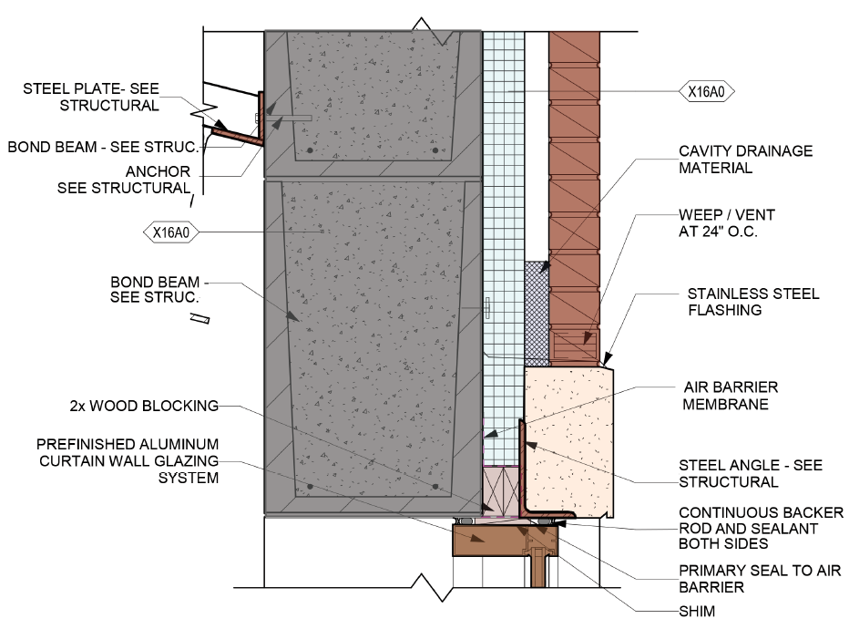 Figure 4. Thermally-efficient window head detail showing long masonry lintel and loose lintel in veneer.
”Sixteen-inch CMU infill walls were used between the large steel columns that support steel roof trusses over 200 feet long. Masonry lintels spanning 13.25-foot-wide windows centered in each structural bay were extended to the full length of the bay. These lintels were prefabricated on-site at two-course height. Then another two courses were added to them after being placed on the wall. The block is not tied to the steel columns at the edges of the masonry infill walls but is connected at the roof diaphragm. This proved to be a critical design decision because the steel frame moved a remarkable 1½ to 2 inches during construction, which would have potentially cracked the masonry wall. The engineer explains, “We had to look at the outward deflection of the steel trusses and compare that to the allowable drift of the CMU wall and find a balancing point where everything worked together. Internal masonry piers adjacent to the steel columns were designed as the boundary elements for the in-plane and out-of-plane lateral loads. Additional piers at the window jambs were designed to carry the out-of-plane lateral loads.”
Summary
The use of masonry for interior walls and backup walls for a masonry exterior veneer proved to be an excellent choice for durability, speed, and cost benefits. Masonry offered the designers a robust solution and allowed the contractor to complete a building during a challenging construction climate with material delivery and price issues for non-masonry products. 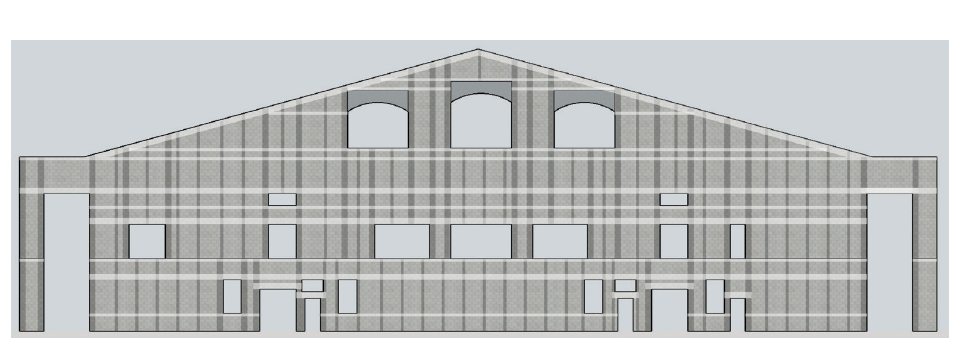 Figure 5. Diagram of long wall showing mid-wall bond beams and extended masonry lintels to restrain CMU movement in lieu of accommodating movement with control joints. Courtesy of FORSE Consulting.
On your next CMU project, challenge yourself to use higher f´m design values reflecting the typical strength of locally available masonry units for more economical and environmentally-friendly use of masonry. Of course, you can always special-order higher strength blocks for special conditions.
 Then consider using lightweight concrete masonry units and masonry lintels to keep masonry projects quick to install, mason-friendly, and low-cost. Lastly, take the time to listen to your mason contractor’s suggestions for creative installation techniques that may benefit the whole project.